Tuesday, August 3, 2021

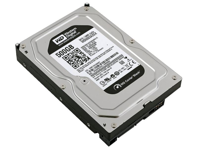
PC-3000 for HDD. Boot ROM mode (COM port) in WD utility for 3.5″ and 2.5″ drives.
 

PC-3000 for HDD. Boot ROM mode (COM port) in WD utility for 3.5″ and 2.5″ drives.                                


79088_0

Sometimes we need to write or read the ROM image, but PCB or SATA adapter are damaged.

There is a way to work with ROM using a special mode – Boot ROM.

1. Let’s see the Boot ROM mode for WD 3,5″ drives.

Power cable is already connected.

Also we need to connect the drive to COM-port.

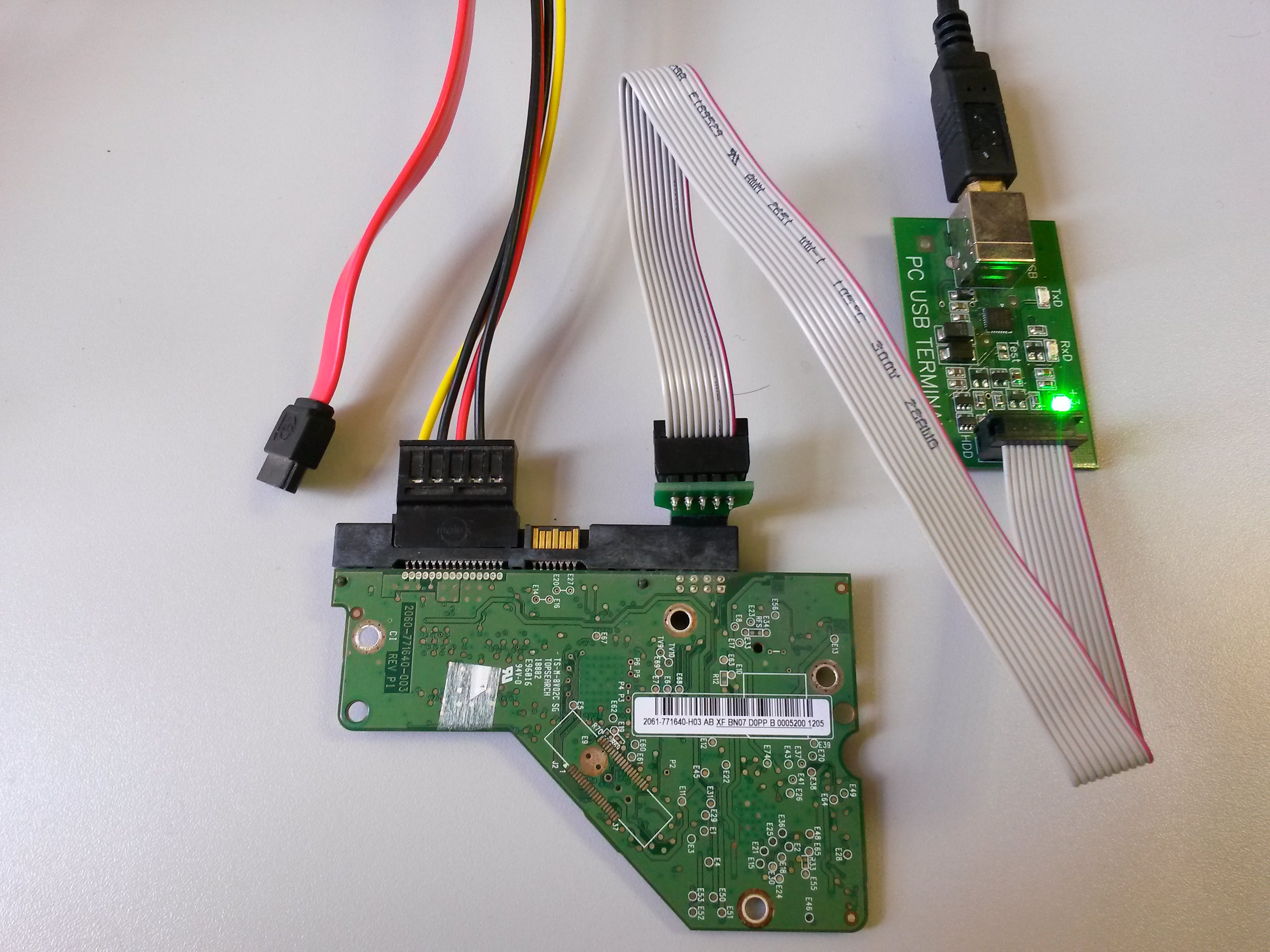
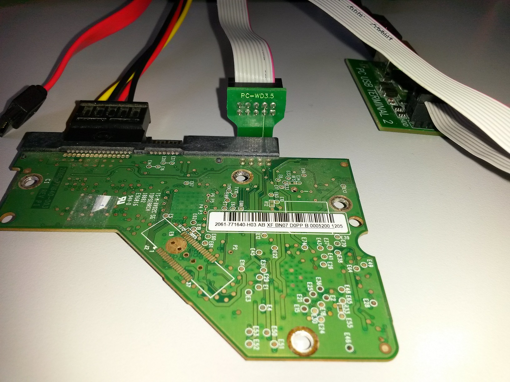
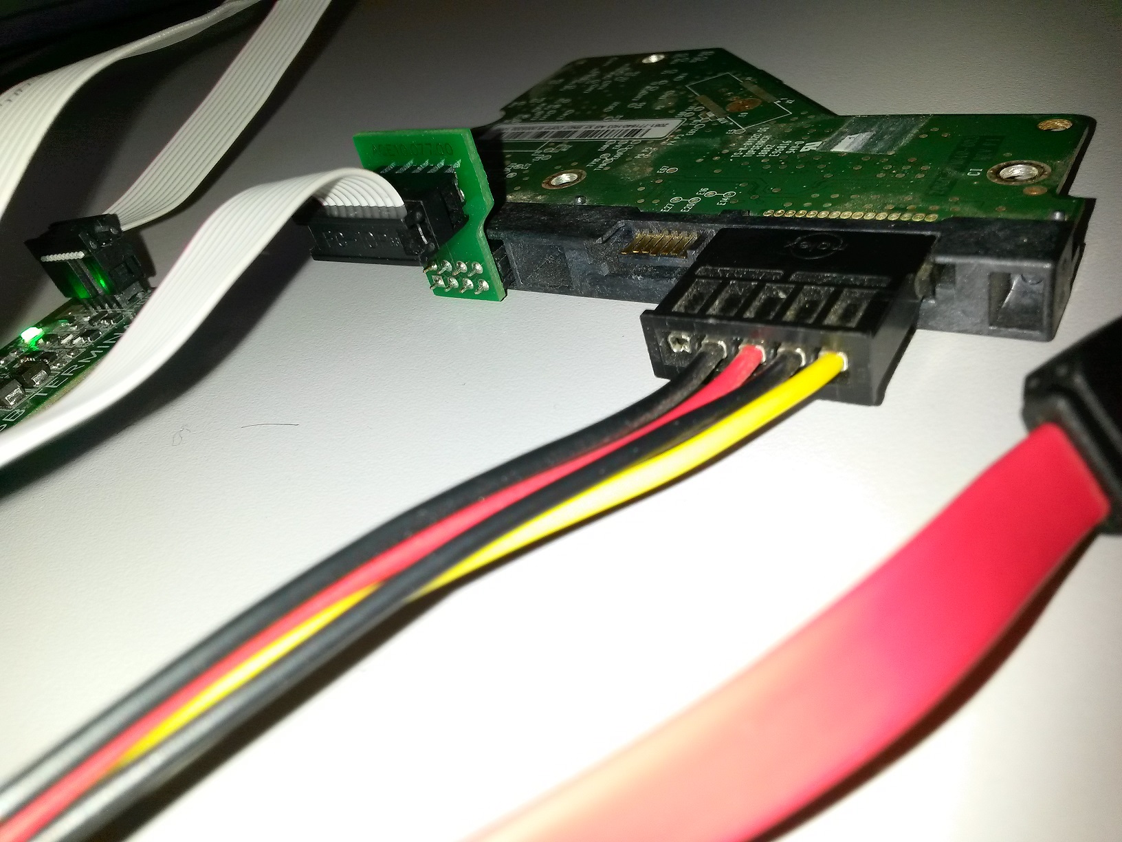
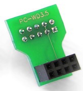
To connect the drive to COM-port we can use PC-WD 3,5″ adapter from PC-3000 kit:
0

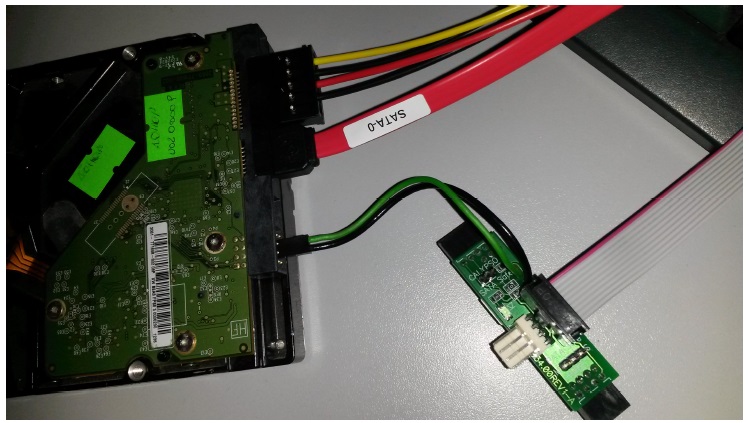
Here is the connection view:

IMG_20160331_134603
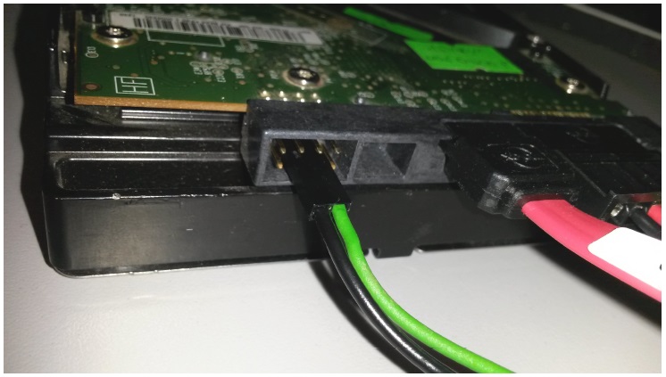
From another side:

IMG_20160331_134636

IMG_20160331_134734

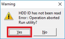
Start the utility. Drive ID does not reading. Press “Yes” button in Warning menu:
1

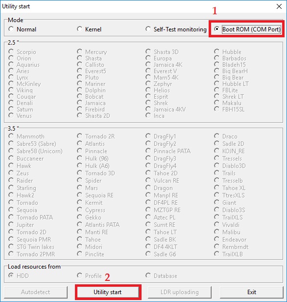
Choose Boot ROM (COM Port) and press Utility start button:
2

After about 10 seconds we can see ROM information:

3

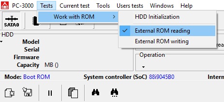
From now we can read the ROM into an image file:
4

Choose the destination folder, enter the name of file, and press Save button.

When the reading is finish, we can see the message about it in log:

5

We can use the new ROM image to analyze it, or write to a donor PCB via SATA or Boot ROM mode as well.

To write the ROM image into a drive we press “External ROM writing” command:

6

We can see the message about writing finish in log:

7


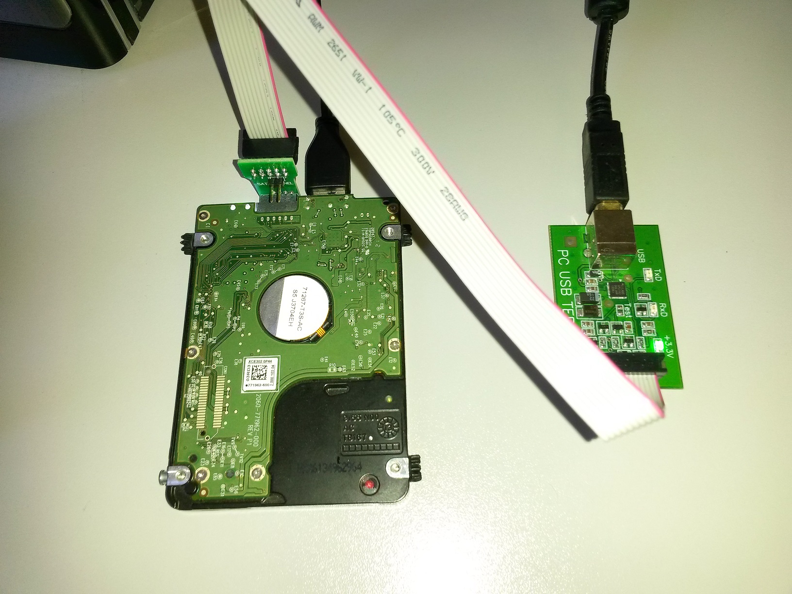
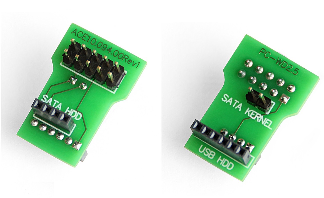
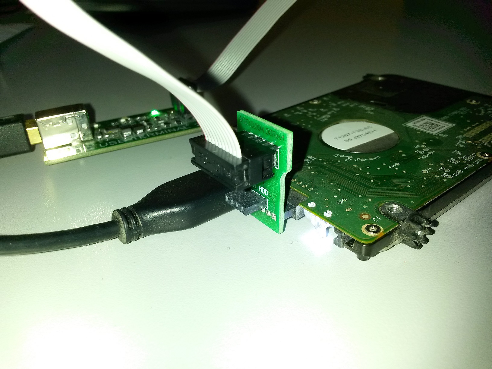
2. Let’s read the ROM from USB PCB using the PC-WD2.5 terminal adapter from PC-3000 kit.
8

Power supply provides via USB cable.
IMG_20160331_145103

IMG_20160331_145157

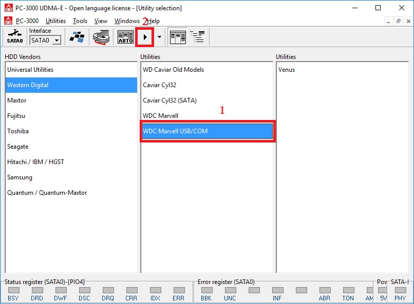
Start WDC Marvell USB/COM utility:

9

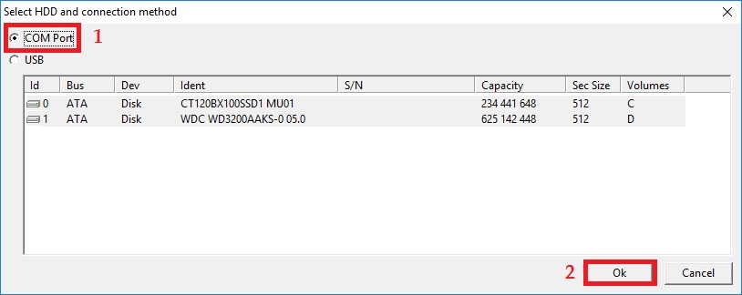
Select the COM port and press OK:

10

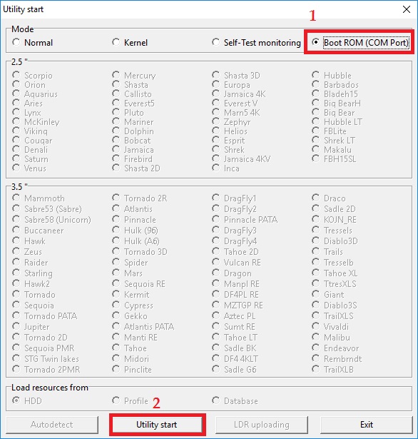
Choose Boot ROM (COM Port) and press Utility start button:
2

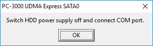
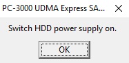
From now the procedure is differs from 3,5” SATA drives. We need to rule the power supply manually to activate the drive initialization. Follow the tips on screen.

Unplug the USB cable from drive and press OK:
11

Plug the USB cable to a drive and press OK:
12

After HDD initialization the ROM is ready for reading and writing:
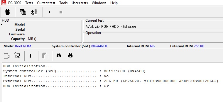
13

Reading and writing procedures are the same as for 3,5” drives.


3. There is a way for ROM reading without PC-WD3.5 adapter from 3,5 WD drives exist.

The procedures of utility start and ROM reading and writing are the same, the difference is only in terminal connection to a drive.

We can use MX-SAFE adapter from PC-3000 kit.14

15

16

Sunday, July 18, 2021

Sample Post


Case Study #16 ST2000DM001- Data Recovery 


Initial Hard Drive Information

PHOTO


https://www.watermark.ws/

https://watermarkly.com/

https://www.picmonkey.com/design/watermark

ST2000DM001 Data Recovery Evaluation

Data Recovery Process

Recovery Time: 3 Days

Percent of Data Recovered: 100%

Total Cost to Customer: $450 (+75 for 1Tb external Toshiba HDD return media)

Raminfotech Data Recovery Lab

102, LB Road,, Adyar, Chennai, Tamil Nadu 600020
Land Mark : Next Ganapathyram Theatre,
044-42116112/3

Ph : 9841983643

email : [email protected]

Media Pickup Center : Omr Porur Madipakkam Ambattur Tambaram  Velachery


Case study 30 seagate  desktop 500gb


LED:0x000000BD FAddr:0x00008608
 

Case study 29- ST2000LM007-1R8174

  Model : ST2000LM007-1R8174
  Serial : WDZGMXGP
  Firmware : SBK2
  Capacity : 2 TB (3 907 029 168)

Tuesday, July 13, 2021

ST1000DM010-2EP102  Seagate Head Replacement


THIS CASE HEAD DAMEGED NOW REPLACMENT HEAD NOW 100% WORKING 
 FULL DATA RECOVERY THIS  HDD CHENNAI COMOPANY HARD DISK


 seagate 1tb

SIM FileFD=FC373028 ErrorCode=43160080 DiscLBA=000000000000ADD1 Duration=000008E6 ms


 No HOST FIS-ReadyStatusFlags 0002A1A1


SIM FileFD=FC375035 ErrorCode=43160080 DiscLBA=000000000000BA47 Duration=0000088D msBailing SOVABusy bit check to avoid hangBailing SOVABusy bit check to avoid hang
 SIM FileFD=FC375035 ErrorCode=43160080 DiscLBA=0000000000032377 Duration=0000087E msMax Wr Retries = 08, Max Rd Retries = 06,  Max Iterations = FF, Max Certify Rewrite Retries = 1172
Ev LBA/Soft XferLen  Zn Trk      Hd Sct  Wdg  PBA      ErrCode


Rst 0x0100MAF11250001    
No HOST FIS-ReadyStatusFlags 0002A1A1IDLE1
F3 T>
ASCII Diag mode

F3 T>
ASCII Diag mode

F3 T>
ASCII Diag mode

F3 T>
ASCII Diag mode

F3 T>
ASCII Diag mode

F3 T>
ASCII Diag mode

F3 T>
ASCII Diag mode

F3 T>
ASCII Diag mode

F3 T>
Boot 0x0100MAF11250001    
SpinUp
 RECOV Servo Op=0100 Resp=0005
 ResponseFrame 1A80 0000 0000 1E00 0000 0000 0000 0000 143C 0000 CE00 0000 CE00 0000 0000 0000 0000 971E 0002 D490 0002 24A8 0004 0001 0000 17E9 0000 0000 0000 0000 0000 0000 0003
TCC:0028

Trans
Tech Unlock Handshake: 0xE498EFAA
Reply:

Rst 0x0100MAF11250001    
No HOST FIS-ReadyStatusFlags 0002A1A1IDLE1


NOT SOLVED ARUL  TB CASE

Monday, June 14, 2021

No HOST FIS-ReadyStatusFlags 2002A1A5

 No HOST FIS-ReadyStatusFlags 2002A1A5


SALVED CASE : 1B 28 35 93 BACKUP  AFTER /M0,6,2,,,,,222 USE AFTER ID DISPLAY 

NOW IMAGE HDD 98% RECOVERY 


Seagate 7200.12 ‘SIM ERROR’ Firmware Fault

The symptoms of ‘SIM Error’ firmware fault from hard drives belong to Seagate 7200.12 family are:

1. Hard drive status keeps BUSY forever after switching on;

2. In the serial command line, it outputs (when PCB is attached to hard drive):

SIM Error 3005
No HOST FIS-ReadyStatusFlags 2002A1A5
ASCII Diag mode

3. In the serial command line, it outputs (when PCB is detached from hard drive):

No HOST FIS-ReadyStatusFlags 2002A1A5

To use the conventional method of fixing a ‘BUSY and LBA=0’ 7200.11 hard drive, it outputs:

No HOST FIS-ReadyStatusFlags 2002A1A5
ASCII Diag mode
F3 T>/2
F3 2>Z
Spin Down Complete
Elapsed Time 6.015 secs
F3 2>
ASCII Diag mode
F3 T>/2
F3 2>U
HighPowerMode
ExecuteSpinRequest
Spin Up Complete
Elapsed Time 3.624 secs
F3 2>/1
F3 1>N1
Init SMART Fail

The initialization of SMART module is failed even though the hard drive passes the Spin up and Spin down operation. To solve this problem, instead of doing N1 to clear the SMART after comand U, we use command m0 first.

(P) SATA Reset

SIM Error 3005
No HOST FIS-ReadyStatusFlags 2002A1A5
ASCII Diag mode

F3 T>/2

F3 2>Z

Spin Down Complete
Elapsed Time 6.035 secs
F3 2>U

HighPowerMode
ExecuteSpinRequest

Spin Up Complete
Elapsed Time 3.573 secs
F3 2>/

F3 T>m0,2,2,,,,,22
Max Wr Retries = 00, Max Rd Retries = 00, Max ECC T-Level = 16, Max Certify Rewr
ite Retries = not supported

User Partition Format Successful - Elapsed Time 0 mins 00 secs

F3 T>/1

F3 1>N1

Clear SMART is completed.
F3 1>
Rst 0x08M
(P) SATA Reset


Friday, June 11, 2021

Removal tool for Kaspersky applications (kavremover)


Removal tool for Kaspersky applications (kavremover)


Download the kavremover tool

Kavremover is a free tool for removing Kaspersky Lab applications that cannot be removed completely using standard Windows tools.


Do not use the kavremover tool unless recommended to do so by Kaspersky technical support engineers.

When you use the kavremover tool, the following information and settings are also removed:

  • License information. Make sure you have the activation code or license key saved before using the tool. We recommend connecting the application to your My Kaspersky account, where your license information will be saved. See this article for instructions. 
  • All application settings. If you want to save the application settings, export them. See the documentation page for instructions on how to import and export settings, using Kaspersky Internet Security as an example.   

Sunday, April 25, 2021

The New PC-3000 Flash Software Ver. 7.5.11 is Available!


The New PC-3000 Flash Software Ver. 7.5.11 is Available!


A SHORT LIST OF THE MAIN ENHANCEMENTS

 ENHANCED SanDisk 8Sec translator for TLC memory algorithm
 ADDED SanDisk 8Sec translator for MLC memory
 ADDED assembly translator algorithm for SM3268 / SM3269 based drives
 ENHANCED SM2704 Translator Algorithm
 ENHANCED SSS6677 Translator Algorithm. Now the assembling algorithm can search the damaged copies of translator tables and reconstruct a working copy from the partially working tables
 ENHANCED PS8210 Translator Algorithm
 ADDED support for NAND QLC Intel / Micron N18 chips
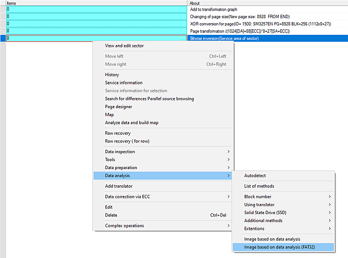
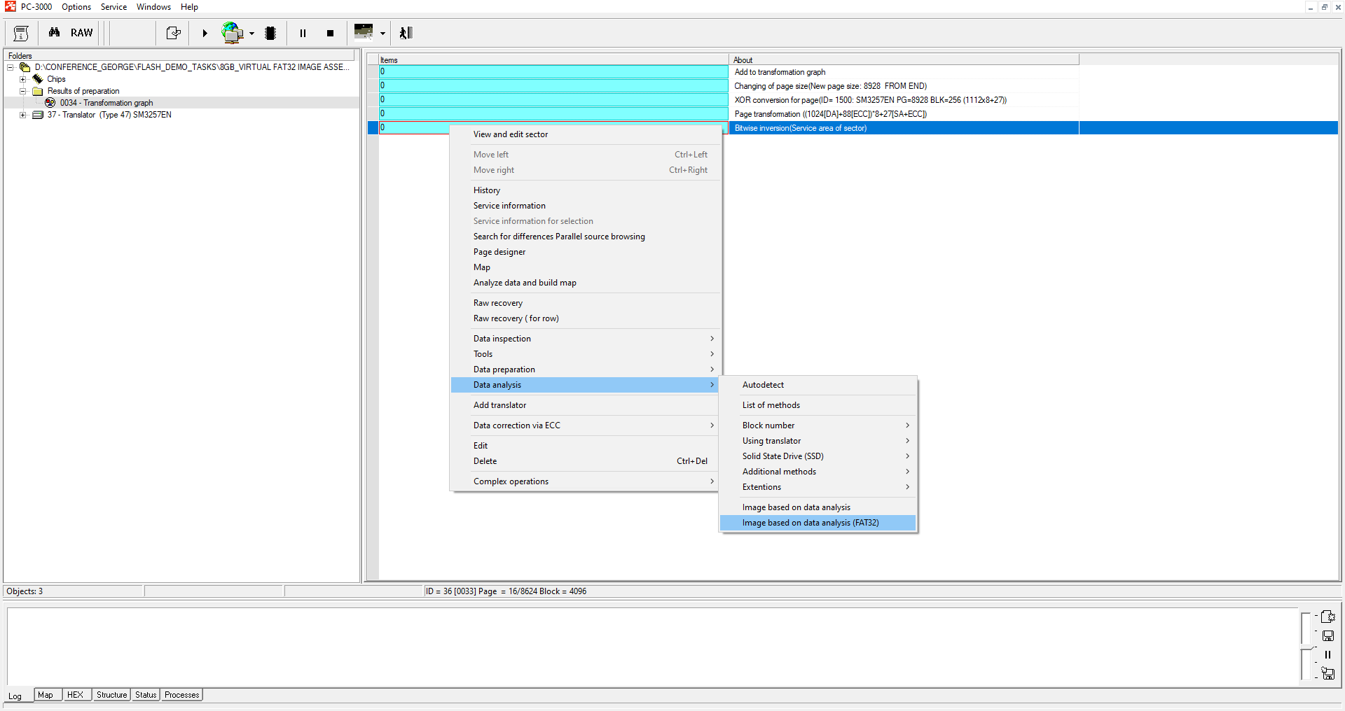
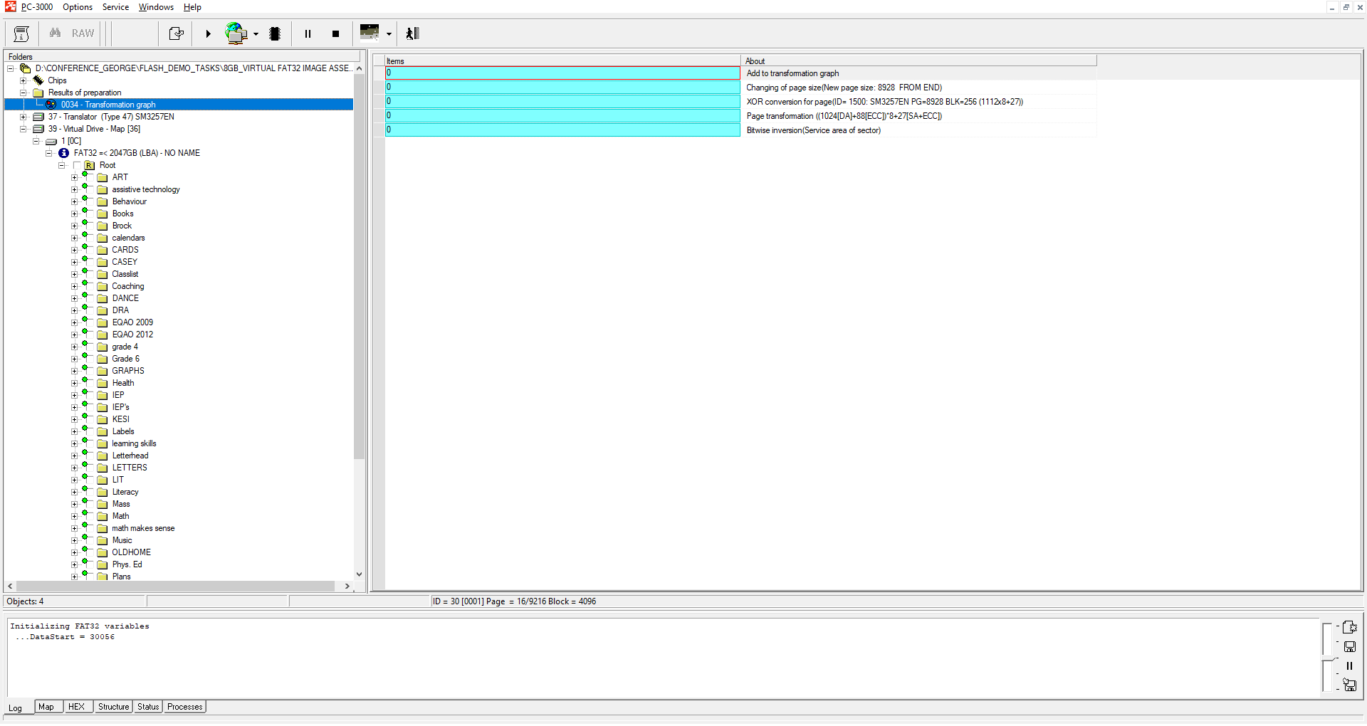
 ADDED a specialized method for data analysis and image building for FAT32-based file systems: “Image based on analysis (FAT32)”
 ADDED BUS pinout detection for the Spider Board adapter.

A DETAILED LIST OF ENHANCEMENTS:

 ENHANCED SanDisk 8Sec translator for TLC memory algorithm:
  • support of new types of firmware and new types of internal structures
  • checking procedure of ECC structures inside the translator tables
  • detailed information about image building procedure now display in log
  • added support of COLB1S5211C1e30r firmware modification
  • added support of COLB1S5211C0t30m firmware modification
 ENHANCED SanDisk TLC translator to work with drives that have offsets in the SLC block
 ADDED SanDisk 8Sec translator for MLC memory:
  • both UFD and SD / MSD drives are supported for image assembling
  • added support for 00ACP01X firmware modification
  • added support for COLB1S5211C1b30o firmware modification
 ADDED the ability to detect the shift of the ROOT folder in the expected place for Sandisk MLC / TLC image building algorithms. Information about the possible shift will be displayed in the log
 ENHANCED image assembling digitalization of the log in Sandisk MLC and TLC translators
 ADDED assembling translator algorithm for SM3268 / SM3269 based drives
 ENHANCED SM2704 Translator Algorithm
 ENHANCED SSS6677 Translator Algorithm. Now the assembling algorithm can search the damaged copies of translator tables and reconstruct a working copy from the partially working tables
 ENHANCED PS8210 Translator Algorithm
 ADDED support for NAND QLC Intel / Micron N18 chips:
  • Intel 29F512G08EBHAF [89D40C32 AA]
  • Micron MT29F1T08GBCAG [2CD40C32 AA]
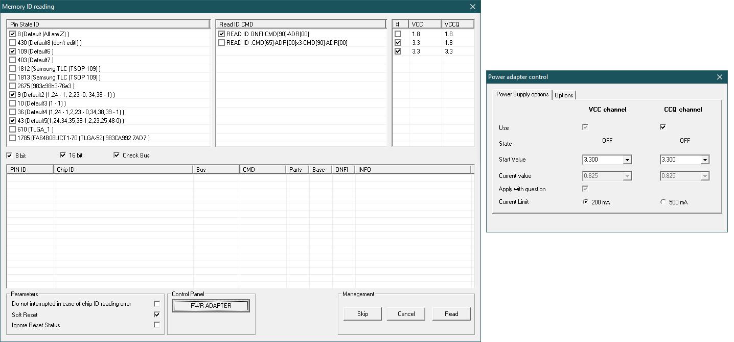
 ADDED the new feature of voltage control in the ID reading mode . Now it is possible to read the ID with 1.8V and 3.3V for VCC and VCCq circuits. It helps to read the new 1.8V NAND chips by default without the necessity to change the power parameters in the PC-3000 Flash Power Control Adapter settings
 ADDED a new algorithm of marker parameters detection for image building by Block Number Type 1 [0000]. It helps to detect the correct mask parameters for different cases
 ADDED a specialized method for data analysis and image building for FAT32-based file systems: “Image based on analysis (FAT32)”

This method, based on deep analysis of FAT structures, in some cases allows you to get a high-quality logical image. The method turns out to be irreplaceable in tasks where there is no translator algorithm for image building or there is no marker in SA area (FC1178/79, SSS6696, SSS6697, SSS6698, TC58NC6623, CBM2199a and other noname controllers). You can learn more about this method in our article

 ADDED BUS pinout detection for the Spider Board adapter. This new feature allows to detect the pins of I/O data lines in case if those pins were unknown. You can read more about this in our article
 ENHANCED the “Visual cutting of sectors in a block” tool. Added auto-detection of clipping formula and group clipping of selected pages by pressing the [Space] key
 ADDED support for basic read commands with a 4-byte block address. This allows you to read large-capacity chips where the block addressing goes beyond 3 bytes
 ADDED the ability to enter values ​​in the hexadecimal form to the dialog for editing the channel synchronization table. A flag that allows you to apply the entered value immediately after entering has been added as well
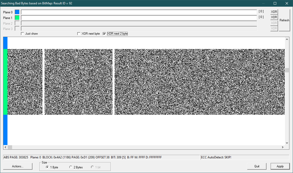
 ADDED an additional “XOR Next 2 Byte” flag in the mode of deleting Bad Bytes by BitMap. It is useful when working with dumps of AlcorMicro controllers
 ADDED the ability to show on the screen the voltage control dialog of the supply circuits simultaneously with Reading the ID of NAND chips. That allows you to control the supply voltage directly in the process of reading the identifier
 ADDED output to the protocol in the reread mode based on external files. That allows you to evaluate which file is applied for each range
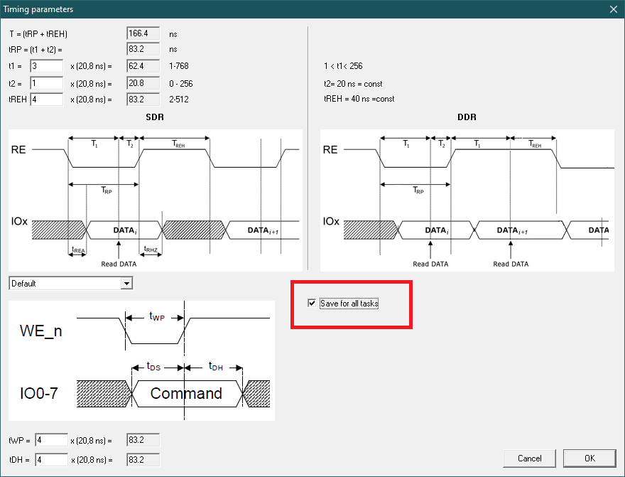
 ADDED a flag to the dialog for editing the protocol time parameters. That allows to save the specified values ​​not only for the current task, but also as initial values ​​for all subsequent tasks
 ADDED Resources:
  • Static XORs